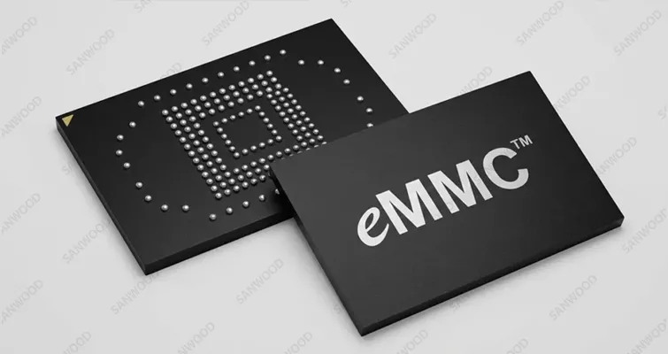
Q1: Why is an active dynamic burn-in system required for eMMC screening rather than a standard static thermal baking oven?
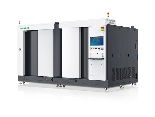
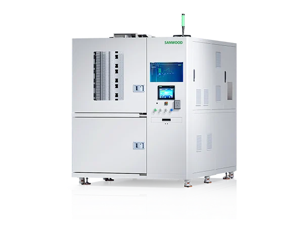
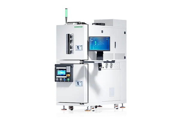
A: Static baking ovens only apply thermal stress to the passive physical structure of the IC. This fails to activate the internal controller, logic gates, and Flash Translation Layer firmware. Latent defects such as gate oxide pinholes, charge leakage paths, and micro-code execution errors only surface when the chip is actively drawing current and cycling data. Sanwood's specialized environmental test chamber layout integrates active digital pattern generators and smart power rails for every slot. By hammering the eMMC devices with continuous write/read vectors while heating, it forces current-dependent and firmware-level anomalies to trip instantly, capturing failures that a static oven would completely miss.
Q2: How does the Sanwood burn-in system isolate a single-slot short circuit or flash controller crash from bricking the adjacent testing array?
A: In high-density memory testing, a single device short circuit can draw massive current, causing voltage drops across the entire bus or even localized fire hazards. Our architecture solves this by integrating an independent, microsecond-accurate over-current protection (OCP) and over-voltage protection (OVP) monitoring circuit for every individual eMMC socket. If a flash controller fails short or draws anomalous current mid-cycle, the localized digital switch instantly isolates that specific slot within microseconds without interrupting power or corrupting data telemetry on the rest of the testing sub-rack.
Q3: What specific engineering design measures prevent high-frequency signal attenuation on the testing backplanes during continuous +125°C exposure cycles?
A: Prolonged operation inside a +125°C climatic test chamber aggressively degrades standard PCB materials, inducing dielectric constant drift and micro-cracking in copper traces, which attenuates critical clock and data lines. To maintain uncompromised signal integrity, Sanwood utilizes military-grade high-Tg polyimide substrate boards with immersion-gold trace finishing. The internal signal lines are route-optimized via balanced differential striplines with impedance controlled tightly within ±5%. This prevents signal reflection and wave distortion across thousands of hours of thermal profiling, securing clean error-free protocol handshakes.
Q4: How does the system accurately map Bit Error Rate (BER) trends alongside micro-ampere standby leakage during high-temperature baking intervals?
A: Tracking device degradation requires real-time telemetry correlation. The system's processing core interleaves the host controller's error correction coding (ECC) logs directly with localized high-resolution current sense amplifiers. During high-temperature hold states, the testing engine commands the eMMC array into standby mode at designated intervals, measuring micro-ampere current leakage. It then instantly boots the drives into full read/write bursts to quantify how many bit slips occurred, mapping a precise multidimensional grid of leakage acceleration versus bit error rate (BER) proliferation.

 English
 中 文
中 文


 info@sanwood.com